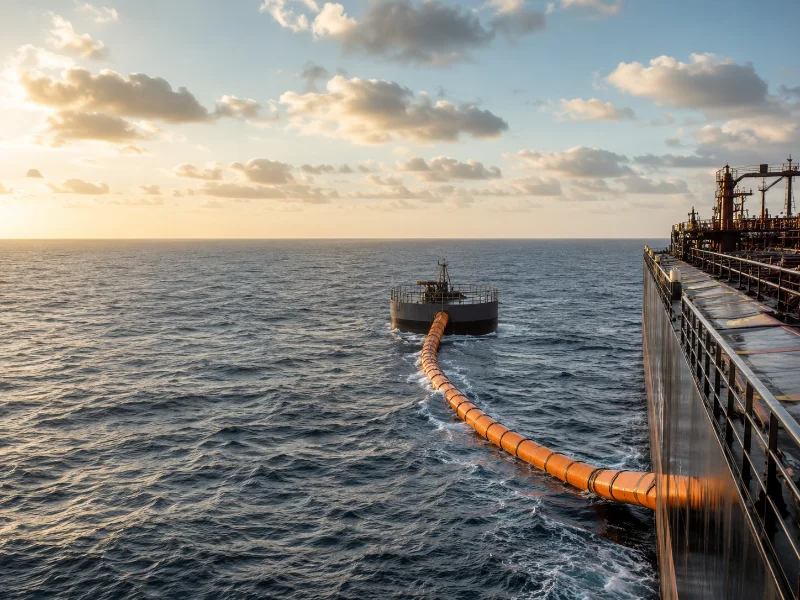
A marine floating hose is a buoyant, flexible hose that carries liquids or slurry across a water surface. It is used where fixed piping cannot follow the movement of a vessel — most often crude oil transfer at offshore moorings and slurry discharge in dredging. Whether a given hose suits a project depends on the fluid, the mooring or discharge configuration, and the reserve buoyancy required at that position in the string. Buoyancy comes either from closed-cell foam built into the hose wall or from external floats clamped onto a standard hose. The right specification is driven less by the hose itself than by where it sits in the transfer string and what it has to survive there.
Floating Hose Definition and Main Applications
A marine floating hose is an elastomer-reinforced hose engineered to stay on the water surface while conveying fluid. What sets it apart from other marine hoses is its buoyancy media, not its bore or pressure class. What varies between designs is how flotation is achieved and how the hose is contained. Those two choices govern visibility, propeller-strike avoidance, and how the line behaves under wave load.
Two applications dominate the search for this term, and they pull the specification in different directions. In offshore oil and gas, floating hoses transfer crude and refined products between tankers, buoys, and FPSO units at mooring systems such as SPM, CALM, and CBM. In dredging, they carry a slurry of sand, silt, and gravel from the dredger to a discharge point. The oil duty is governed by hydrocarbon-hose standards and leak containment; the dredging duty is driven by abrasion resistance and slurry velocity. Which duty applies matters, because a hose built for one is not automatically fit for the other.
Floating hoses stay visible on the surface, which helps vessel operators steer clear of the line and avoid propeller contact. That visibility is a working safety function, not a cosmetic one. It does not make the hose immune to a strike, though — propeller cuts remain one of the documented ways a surface hose is damaged. That is exactly why the line is floated, colored, and kept clear of the vessel rather than left loose in the water.
Three Separate Ways to Classify a Floating Hose
Floating hoses are classified along three independent axes: buoyancy method, containment construction, and position in the string. Treating these as one combined category is the most common specification error. Buoyancy method and carcass construction are separate decisions. One governs how the hose floats, the other governs how a leak is contained, and neither determines the other.
Buoyancy method is the first axis. A floating hose may use closed-cell buoyancy material built integrally around the hose body, or, in some applications, discrete external floats fastened onto a standard hose. Integral foam is bonded to the hose body and cover. Clamp-on floats can be added or removed as a project changes. The two also fail differently, so they are inspected differently. Clamp-on floats add mechanical fixing points that can loosen, chafe, or shift along the hose. An integral-foam wall has no such fixings, but once its outer cover is breached it can take on local water ingress that is hard to reverse on site. Because the buoyancy is either bolted on or built in, there is no universal “better” choice. It depends on who inspects the line and how often.
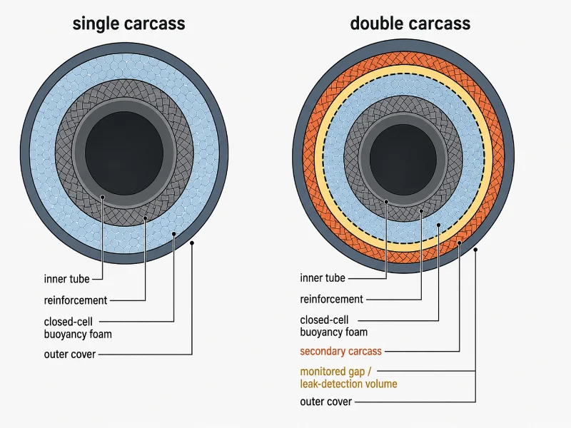
Containment construction is the second axis, and it is separate from buoyancy. A single-carcass hose has one containment layer. A double-carcass hose adds a second carcass with a monitored volume between the two. The double-carcass design exists for leak containment, not flotation. If the primary carcass develops a slow leak or a sudden burst, the secondary carcass holds the escaping fluid, and a leak-detection or failure-alert device signals the operator. A double-carcass hose can get its buoyancy from integral foam or from floats, so the containment choice does not dictate the buoyancy choice.
Position in the string is the third axis. It sets the hose’s shape and duty rather than its material. Mainline, tail, tanker rail, and first-off-buoy sections are all floating hoses. But each carries a different reinforcement and buoyancy specification, because each sits in a different part of the transfer path. The next section covers those positions.
How a Floating Hose String Is Arranged
A floating hose rarely works alone. It functions as one link in a hose string, and each section has a distinct shape and duty. So a purchase order for “a floating hose” is usually really an order for several different hoses in sequence. Getting the section wrong for a position is a specification error even when every individual hose is sound.
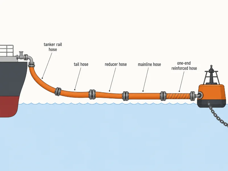
A complete offshore string generally runs from the tanker outward through sections whose names recur across the industry:
- Tanker rail hose — hangs from the tanker’s side rail and couples to the ship’s manifold, flexing under its own weight to bend close to the manifold; effectively the joint between ship and floating string.
- Tail hose — a highly flexible section that accommodates buoy or manifold movement, often the first connection off a mooring buoy.
- Reducer hose — connects two hoses of different diameters where the bore changes; not always present in a string.
- Mainline hose — the primary buoyant conduit making up the bulk of the surface line.
- First-off-buoy / one-end reinforced hose — carries extra reinforcement concentrated at the connecting end, used at buoy or FPSO connection points.
The reinforced-end section is worth a closer look. Its reinforcement sits at the end that attaches to the buoy or manifold, because that connection point is where bending moment and axial load concentrate. Strengthening that end manages the strain that would otherwise build up right there. Reinforce a hose evenly along its whole length and you add stiffness where it is not needed, yet it is still most loaded at the joint. That is why the reinforcement is placed asymmetrically instead.
Dredging strings are simpler, but the abrasion demand is higher, because the line carries solids rather than oil. Dredge floating hoses rely on abrasion-resistant inner linings to survive the high-velocity movement of sand and gravel. Their buoyancy keeps the pipeline off the seabed, so it is not worn down by dragging.
Reserve Buoyancy: What “20%” Actually Means
Reserve buoyancy describes a hose’s residual buoyancy when flooded, expressed as a margin above its flooded weight. The required figure depends on the hose’s position in the string rather than being one universal number. A hose that floats when empty can still sag when full of dense fluid, which is why buoyancy is specified as a flooded-condition margin, not a yes/no property.
Under GMPHOM 2009, fully floating offshore mooring hoses carry a minimum reserve buoyancy commonly cited as 20% under the flooded condition. The buoyancy material is distributed over the whole length, so the hoses float evenly in a string. That reserve figure includes the weight of any hardware attached to the hose, such as flanges and couplings, not the bare hose alone. Part-floating hoses used at buoy connections are treated differently. The standard does not fix a universal percentage for them. Buoyancy is based on the specific site criteria and defined by the purchaser, and it is usually applied over part of the hose length unless otherwise agreed. Low figures such as 5% do appear on some individual product data sheets. But they should only be quoted where the relevant data sheet or purchase specification supports them — never assumed as a default.
Reserve buoyancy is a margin above flooded weight, so heavier cargo and larger bore both eat into that margin from the same direction. A hose comfortably buoyant on a light refined product can approach its limit on high-density crude at the same diameter. That is why a buoyancy percentage cannot be read in isolation from the fluid the hose will carry. A bare figure on a data sheet does not tell you the margin under load.
Floating Hose vs Submarine Hose
A floating hose stays on the water surface, while a submarine hose is designed to run below the surface toward the seabed. Confusing the two leads directly to a hose that cannot do its intended job. The difference changes the buoyancy design, the reinforcement, and where the hose sits in the mooring system. It is not a minor variant.
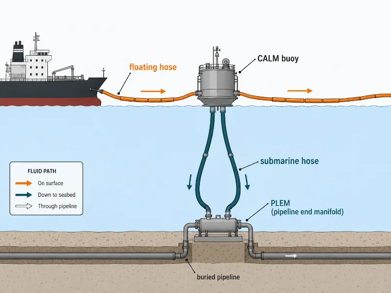
Floating hoses connect surface equipment: tanker to buoy, buoy manifold to shuttle tanker, or dredger to discharge point. Submarine hoses run downward from the buoy toward the seabed pipeline end manifold (PLEM), carrying fluid the final leg to the fixed subsea line. They are built for external pressure and abrasion rather than surface visibility. Submarine strings do not always lie flat on the bottom either. Depending on water depth and dynamics, they may hang in suspended configurations between buoy and seabed. But their detailed configuration, ballasting, and installation belong to a separate submarine-hose specification and are not interchangeable with surface floating-hose selection.
In a typical CALM buoy installation, both types work in the same system: submarine hoses run between the PLEM and the buoy, and floating hoses run between the buoy and the tanker. Whether submarine sections are needed at all comes down to the complete transfer-system architecture, not the floating hose on its own. Ship-to-ship and some dredging setups can run with a surface hose string only; a moored offshore terminal generally cannot. A floating hose earns its cost over rigid piping where laying fixed pipe is impractical or uneconomic and the line has to follow a vessel’s movement. Adding hose complexity the mooring geometry does not need is a cost without a return.
Which Standards Apply?
The standards below apply to offshore hydrocarbon hose systems. Floating dredge hoses are specified through a separate abrasion- and slurry-based process rather than these hydrocarbon-hose documents. For offshore mooring service, three standards recur, each with a distinct scope. Which one to cite depends on what the hose actually is.
OCIMF GMPHOM 2009 is the principal purchasing and qualification guide for elastomer-reinforced oil suction and discharge hoses at offshore moorings. It is the Oil Companies International Marine Forum’s Guide to Manufacturing and Purchasing Hoses for Offshore Moorings, now in its 5th edition. It standardizes how these hoses are manufactured, tested, and purchased. OCIMF adds one caution itself: it does not control the stamping of “GMPHOM 2009” on hoses. A buyer should run due diligence to confirm the hose specification is really as claimed, rather than trust the marking alone.
EN 1765:2016 specifies four types of rubber oil suction and discharge hose assemblies for petroleum, including crude oils, with a maximum aromatics content of 50% by volume. It covers nominal bores from 50 to 500 and a service temperature range of −20 °C to 82 °C. It is explicitly not intended for LPG or natural gas. It is a common European reference for dock and marine oil hoses.
API Spec 17K, Specification for Bonded Flexible Pipe, covers bonded flexible pipe assemblies with end fittings at both ends. It applies to flowlines, risers, jumpers, and offshore loading and discharge hoses. It does not cover unbonded flexible pipe. It also does not compete with GMPHOM: API 17K states that supplementary requirements for loading and discharge hoses can be found in GMPHOM, provided they do not contradict API 17K. So on a bonded, production-grade offloading hose, the two are read together. API 17K governs the bonded-pipe requirements, and GMPHOM supplies the mooring-hose specifics.
Where a project references a minimum bend radius, that figure is hose-design specific and should come from the approved manufacturer’s data sheet or project specification. Values such as six times the nominal diameter (6D) appear on some offshore hose designs, but they are not a universal GMPHOM requirement.
Prototype Qualification vs Production Acceptance Testing
Hose testing under GMPHOM splits into two categories that serve different purposes, and blurring them misleads a buyer about what every delivered hose has actually undergone. Production acceptance tests are applied to purchased hoses. Prototype qualification tests are applied to a hose design, to prove the type — not to every unit shipped.
Production acceptance testing for purchased hoses draws on a defined battery: adhesion, weight, minimum bend radius, hydrostatic, vacuum, electrical continuity, and flotation-related tests among them. Certain additional tests, such as torsion, kerosene, or tensile, apply only when the purchaser specifies them. So “tested to GMPHOM 2009” means something only when the specific tests applied are named, because the optional items change what has actually been verified.
Prototype qualification is a separate, more demanding process applied to the design. Dynamic tests, such as dynamic bending, tensile, and torsion evaluation, are part of qualifying a hose type rather than routine testing of each delivered hose. A buyer should not read a design-qualification test as something done to every unit in a purchase order, nor assume routine acceptance covers the full prototype programme. If a supplier cannot say which category a quoted test belongs to, that gap is worth closing before the order goes in.
Electrical continuity deserves a specific note, because it is specified both ways. A floating hose may be built electrically continuous or discontinuous depending on the project’s grounding and bonding scheme. This is a project decision, not a fixed property, and it should be defined as part of the wider earthing arrangement rather than assumed.
How to Specify a Floating Hose
Specifying a floating hose comes down to resolving inputs in the right order. The early decisions are largely irreversible; the later ones can be adjusted once the early ones are fixed. The controlling first input is the fluid and its flow conditions. Fluid type, flow rate, pressure, and solids characteristics all feed into bore, liner, reinforcement, buoyancy margin, and the applicable standard.
Confirm the first layer before anything else — the fluid and flow conditions:
- Fluid composition, density, viscosity, and aromatic or chemical content
- For slurry: particle size, concentration, and abrasiveness
- Required transfer rate and allowable flow velocity
- Rated working pressure, surge pressure, and any vacuum condition
- Minimum and maximum fluid and ambient temperature
These are largely irreversible design inputs. A liner and bore chosen for crude at one flow rate cannot simply be re-rated later for an aggressive chemical or a higher-velocity slurry.
Then fix the second layer — the system position and environment. This covers the mooring or discharge configuration (SPM, CALM, CBM, ship-to-ship, or dredge discharge), the hose’s position in the string, vessel motion, water depth, waves, current, and the weight of ancillary equipment that counts toward buoyancy. Position dictates which section you need (tanker rail, tail, mainline, or first-off-buoy) and which reserve-buoyancy figure you are actually buying.
Bore, length, carcass construction, liner, reinforcement, reserve buoyancy, minimum bend radius, flange class, and electrical configuration are the third-layer outputs. Bore is not a free choice made last. It follows from flow rate, allowable velocity, and pressure loss in the first layer, but it is settled once those upstream inputs are pinned down. The trap to avoid is specifying from diameter and price first. When the load-bearing decisions are made last, the resulting line is the one most likely to come back for early re-checking or replacement.
One more honest point about scope: for a short, sheltered transfer where a fixed line or a simple dock hose would serve, a full floating mooring hose string is overkill. The floating design earns its cost in open water, dynamic sea states, and moorings where rigid pipe cannot follow the vessel. Matching hose complexity to the actual site is part of specifying it correctly.
Inspection, Storage, and Repair Boundaries
Floating hose service life is governed by condition rather than a fixed calendar figure, and it is confirmed through inspection. The controlling variables are exposure, cargo, handling, and sea state. Scheduled visual checks and pressure tests are what establish remaining life, because two hoses of the same age can be in very different condition depending on how hard they have worked.
Storage before installation affects a hose’s starting service life, and the controlling factors are sunlight, temperature, and physical stress. Hoses keep best indoors, in a dry, cool, ventilated space. Where outdoor storage is unavoidable, they should be kept out of prolonged direct sunlight and coiled to avoid sharp bends. Storage duration and pre-installation checks should follow the manufacturer’s instructions and the project hose-management plan rather than a generic time limit.
Repair boundaries depend on whether damage stays in the cover or reaches structural layers. Assessed non-structural cover damage can sometimes be repaired under an approved procedure, but only after confirming the reinforcement, carcass, end fittings, buoyancy structure, and any leak-detection system are intact. Damage that reaches those elements calls for withdrawal from service and review by the manufacturer or another competent authority. Repairing an outer cover does not, on its own, restore the hose’s original certified condition.
Where to Start With Floating Hose Selection
Specifying a floating hose comes down to resolving two things before the rest: what the hose carries, and where it sits in the transfer string. Bore, length, and couplings follow from the fluid, flow conditions, and position. Reserve buoyancy and liner material are consequences of those inputs, not independent choices. The recurring failure is specifying from diameter and price first, which leaves the load-bearing variables decided last.
As a marine equipment supplier, our part at this stage is to confirm the specification against the mooring or dredging configuration rather than quote a bore off a table. The fluid, sea state, and mooring position determine which section and which buoyancy rating actually fit. Several of these inputs need project-level checking against the hose-system designer’s requirements, not a catalogue default. For the surrounding mooring and offloading components a floating hose connects to, our Marine Equipment range covers the adjacent equipment on the terminal side.
To move from reading to a real quotation, it helps to have these inputs ready:
- Fluid type, density, viscosity, and aromatic or chemical content
- Solids (for slurry): particle size, concentration, abrasiveness
- Flow: required transfer rate and allowable velocity
- Pressure: rated working pressure, surge pressure, vacuum condition
- Temperature: minimum and maximum fluid and ambient
- Hose position and system: mainline, tanker rail, tail, first-off-buoy; SPM, CALM, CBM, STS, or dredging
- Environment: water depth, waves, current, and vessel motion
- Reserve buoyancy requirement, including the weight of attached hardware
- Electrical continuity preference (continuous or discontinuous)
- Governing standard: GMPHOM 2009, EN 1765:2016, API 17K, or project specification
With those in hand, the specification stops being guesswork. It becomes a matter of matching known conditions to the right hose section and rating.
FAQ
Service life is set by condition and duty rather than a fixed number of years, so two hoses bought together can retire years apart. Manufacturers commonly design mooring hoses for a structural life of up to around ten years under normal service, and OCIMF guidance points toward removing hoses for a full inspection after an initial period in the region of five years. Both are reference points, not guarantees. Cargo, UV exposure, sea state, and handling move the real figure, and a hose that has taken a propeller graze or been over-bent on deck can fall due well ahead of an identical hose in gentler service.
Inspection frequency is driven by the hose’s exposure and criticality, not a single calendar rule, and it usually layers routine and periodic checks. Frequent visual checks catch surface damage — cover cuts, flange condition, float security — between the deeper periodic tests that requalify the hose’s pressure integrity. The interval a specific terminal uses should follow its hose-management plan and the manufacturer’s guidance, and it tightens for double-carcass hoses in environmentally sensitive service where a missed leak is costly.
Whether a hose stays on site or goes back comes down to how deep the damage runs, so the decision starts with assessment, not a patch. A superficial mark on the outer body, one that has left the steel carcass and reinforcement untouched, may qualify for a controlled field repair. Repair work of this kind is best done somewhere dry and dust-free so the bond holds. Anything reaching the carcass, end fittings, or buoyancy layer sends the hose back for manufacturer review, and a passed cover repair still does not hand back the hose’s original certificate on its own.
Floating hose failures cluster around a few mechanical and environmental modes rather than sudden material defects. Cover abrasion reaching the reinforcement, flange wear, kinking from over-bending, and propeller cuts build up with UV exposure, handling, and sea state. That pattern is why routine inspection targets the cover surface, flange area, and buoyancy elements first.
Floating and submarine sections age at different rates, so they are not automatically renewed together. Surface floating hoses take the brunt of UV, vessel contact, and wave action, while submarine sections face different loads lower in the string. Each section is tracked on its own condition record, which is why a string is often built for section-by-section replacement rather than a single full-length swap.