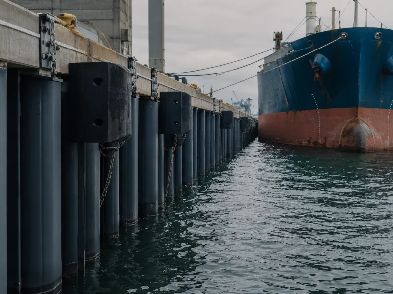
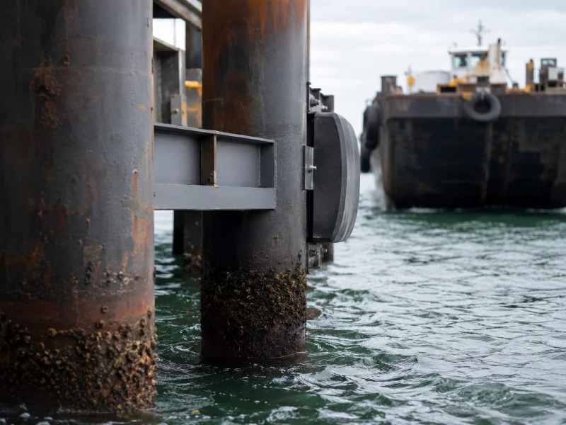
Steel fender piles are steel pipe, H-section, or wide-flange piles driven along a berth to keep vessels off a pier, wharf, quay, or dolphin. They form part of a marine fender system and take berthing impact through bending, deflection, and load transfer. How well they perform depends on section size, embedment, corrosion protection, and the pneumatic fender, rubber, or foam unit paired with them. This article explains what steel fender piles are, the forms they take, how they compare with timber and concrete, and what to check before you specify steel. It does not cover pile-driving or embedment design, which depend on site geotechnics and belong in a separate structural review.
What steel fender piles are and how they protect a berth
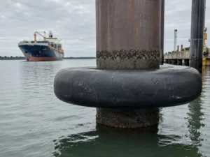
Steel fender piles are structural steel sections driven along a quay or wharf, where their protective role depends on section type, embedment, and connection to the fender unit. The system holds a docking vessel at a controlled standoff, passes berthing loads into the supporting structure, and works with the fender so both the berth and the hull stay protected. A fender pile is not the same member as an anchor pile, which restrains sheet-pile walls instead of taking berthing impact.
We tell clients early that the pile is one element in that system, not a standalone bumper. The berthing energy a fender line can absorb depends on pile length, penetration, and material stiffness. Change any one of these, and the energy the line can safely handle changes with it. That makes material selection a structural decision to verify against the design vessel, not a cosmetic one.
Why a steel fender pile is rarely the sole energy absorber
Steel fender piles resist impact through bending and load transfer, but in most modern berths they are not the sole energy-absorbing element, because their elastic deflection is limited. A steel section is strong and bends predictably. That deflection, though, is capped by yield stress, fatigue, connection details, corrosion allowance, and the reaction the berth structure can accept.
For that reason, engineers check the required berthing energy across the whole system: the pile, the rubber, foam-filled fender, or pneumatic unit, the wale or panel, and the supporting structure. Specify a steel pile as if it were the cushion, without a fender to provide deflection, and the arrangement turns rigid. The rigid pile then drives berthing loads back into the structure it should protect, which usually forces a redesign after the first hard berthing.
We check the combined pile-and-fender deflection budget against the design berthing energy before recommending steel, rather than judging the pile on its own. The test is simple: confirm the fender adds enough movement to meet the design berthing energy, and confirm the residual load on the structure stays within capacity.
Steel fender pile forms and their typical uses
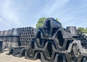
Steel fender piles come mainly as pipe piles, H-piles, and wide-flange sections, and the right form depends on the required strength, the drivability at the site, and the corrosion allowance the exposure demands:
- Pipe piles, specified to a steel pipe-pile standard such as ASTM A252, give a large, consistent section and are common where deep water or point-bearing capacity governs.
- H-piles or wide-flange sections suit sites where drivability through hard strata or obstructions governs. Their exposed flanges, web, and connections need extra corrosion and local-bending review in marine service.
- Coated or wrapped sections — epoxy or coal-tar epoxy coatings, HDPE or UHMWPE sleeves, or petrolatum-tape wraps — suit sites where corrosion exposure is high but large deflections are not expected.
- Added corrosion allowance and cathodic protection — thicker walls plus sacrificial or impressed-current systems — suit sites where submerged section loss would otherwise govern the design.
ASTM A252 confirms the pipe-pile product requirements. It does not, on its own, verify berthing energy, corrosion design life, embedment, or fender-system performance. We match the section to both the load and the driving conditions on site, because the profile that drives best is not always the one that pairs best with the chosen fender.
How steel compares with timber and concrete on the variables that drive selection
Choosing between steel, timber, and concrete fender piles turns on a few decision variables, not a single best-material verdict: corrosion exposure, energy absorption, water depth and load, and lifecycle maintenance. The material that looks strongest on a datasheet can lose once splash-zone corrosion or driving conditions come into play, so tie the comparison to the project.
| Decision variable | Steel | Timber | Prestressed concrete |
|---|---|---|---|
| Corrosion / deterioration | Section loss, worst in splash and tidal zones, unless coated and cathodically protected | Decay and marine borers without preservative treatment | Chloride ingress and reinforcement corrosion if cover or mix is inadequate |
| Deflection and energy | Predictable bending, limited elastic deflection, usually paired with a fender | Flexible; traditional pile-fender use; moderate absorption | High stiffness; prestressed piles can absorb high energy when designed as pile fenders |
| Depth, load, drivability | High; suits deep water and hard driving | Moderate; easier handling, smaller berths | High capacity but heavier and more brittle to handle |
| Lifecycle maintenance | Coating and cathodic-protection upkeep; splash-zone inspection | Preservative and borer protection | Crack and cover inspection |
We compare the three against the exposure and load profile of each project, because a choice made on reputation alone rarely survives the site conditions. Steel earns its place where strength, depth, or hard driving dominate. Timber and concrete often win where those pressures are lower or maintenance access is limited. Fibre-reinforced composite piles are a further option where corrosion resistance comes first, though you should check availability and product-specific limits.
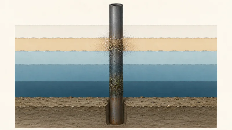
Corrosion protection across marine exposure zones
Steel fender pile corrosion is not uniform along the pile; it concentrates by exposure zone, so protection that suits one elevation can be wrong for another. Treating the pile as a single corrosion condition is one reason coating budgets end up too low where attack is worst.
| Exposure zone | Main risk | What to verify |
|---|---|---|
| Atmospheric | UV, salt spray, coating chalking | Coating system and inspection interval |
| Splash | Wet-dry cycling, oxygen, abrasion — the most aggressive band | Coating, wrap, corrosion allowance |
| Tidal | Alternating immersion and exposure | Coating continuity and section loss |
| Submerged | General corrosion and biofouling | Cathodic protection and inspection |
| Mudline | Local corrosion, scour, higher bending demand | Section-loss allowance and embedment review |
We set the coating, cathodic protection, and corrosion allowance by zone rather than one blanket figure. In service, the splash zone is the first place we re-check coating integrity.
When steel is the right choice, what to verify, and mistakes to avoid
Steel fender piles are usually the stronger option where deep water, hard driving, or high berthing loads exceed what timber or concrete can handle, as long as the corrosion protection and the pile-plus-fender pairing are verified for the design life. The strength and drivability that make steel attractive also make it stiff, so the specification only holds once the pairing and protection are confirmed.
Before committing to steel, we recommend verifying four things:
- The coating and cathodic-protection system are specified by exposure zone, splash zone first.
- The pile-and-fender deflection budget meets the required berthing energy.
- The section suits both the load and the expected driving conditions.
- The corrosion allowance matches the target service life rather than an assumed figure.
Several public references support these checks, though none replaces project-specific design. ASTM A252 covers the pipe-pile product. PIANC and BS 6349-4 cover fender-system and berthing-energy design. UFC 4-152-01 covers US Department of Defense waterfront facilities, so treat it as a defense reference rather than a universal commercial-port code. AISC covers structural-steel section checks, and ISO 12944 covers coating and corrosion-protection planning.
The specification errors we see most often are:
- treating ASTM A252 as a complete fender-system design standard
- picking the pile section before the berthing energy is calculated
- leaving out a splash-zone corrosion allowance
- assuming steel stiffness means higher energy absorption
- designing the pile and the fender separately instead of as one load path
We align the pile specification, the fender unit, and the corrosion strategy as a single decision, so the pile is never checked against the wrong requirement.
Conclusion
Choosing steel fender piles is a decision about deflection, corrosion, and load, not material preference. Those three variables, more than any single spec line, decide whether steel beats timber or concrete on a given berth.
In our own project reviews, section loss on steel piles shows up first in the splash and tidal zones. That is why we treat coating integrity there as something to re-check, not assume. Where berthing energy, service life, or driving conditions are still open, those stay project-level variables to confirm before the specification is fixed.
If you are specifying a fender system for a new or upgraded berth, bring the key inputs together so the pile, the fender, and the corrosion strategy can be checked as one: design vessel and berthing velocity, water depth and tide range, target service life, and inspection access. As a Marine Equipment Supplier, our team can review those inputs and align the steel fender pile specification with the rest of your marine fender system. Contact us to submit your berth requirements for review.
FAQ
Steel fender piles are usually a load-transfer element, not the main absorber. In most berth designs the pile provides limited deflection, while the paired rubber fender, foam, or pneumatic unit supplies most of the energy absorption. The berthing-energy check then covers the pile, the fender, the wale, and the structure together.
A fender pile absorbs and transfers berthing impact along the outer line of a berth, while a bearing pile carries vertical structural load into the ground. The two are governed by different load cases, so a member sized as a bearing pile is not automatically suitable as a fender pile.
A steel pipe pile suits deep water and high point-bearing demand, where its large, uniform section helps. An H-pile fits sites where driving through hard strata or obstructions is the main constraint, though its exposed flanges and web call for closer corrosion review in the splash zone.
Steel fender piles in submerged service usually pair cathodic protection with a coating system, and the exact choice depends on exposure, design life, and inspection access. The submerged and mudline zones are where cathodic protection most often justifies its cost.
Steel fender pile embedment is set by seabed conditions, load, and the required height above the mudline, not by a fixed figure. Because this article does not cover embedment design, confirm the depth through geotechnical and structural analysis for the specific berth.
Steel fender piles win on strength and depth, but not automatically on lifecycle cost. They are the stronger pick for deep water, high load, or hard driving. On smaller, low-exposure berths with limited maintenance access, timber or concrete often gives a better long-term result.