Pneumatic fenders, also known as Yokohama fenders, use air as a medium to absorb impact forces, making docking operations more flexible and preventing collisions. These fenders are known for their high energy absorption, low reaction force, simple installation, good elasticity, no deformation, lightweight, and cost-effectiveness. They are widely used on oil tankers, container ships, luxury yachts, offshore platforms, large docks, and naval ports, becoming an indispensable part of ship and port protection.
Basic Uses of Pneumatic Fenders
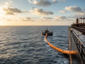
Pneumatic fenders are primarily used to reduce impact forces and protect both the ship and the dock. During docking or undocking, pneumatic fenders effectively absorb impact forces, minimizing damage to the ship and dock. Additionally, they provide flexible protection to the hull, preventing wear and damage caused by direct hard contact. Common applications are:
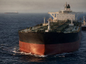
- Oil tankers
- High-speed ferries
- Temporary and permanent facilities
- Ports with significant tidal changes
- Ship-to-ship transfer operations
- Naval vessels
Choosing the Right Pneumatic Fender Size
Correct sizing is the single most important factor in pneumatic fender performance. An undersized fender cannot absorb sufficient berthing energy. An oversized fender wastes budget and complicates handling.
Fender selection starts with calculating the design berthing energy based on vessel displacement, approach velocity, berthing angle, and environmental conditions. The PIANC (World Association for Waterborne Transport Infrastructure) guidelines provide the standard methodology for this calculation.
Recommended Sizes for Small and Medium Vessels
| Displacement (DWT) | Recommended Size D × L (m) | Typical Vessel Type |
|---|---|---|
| 500 | 0.5 × 1.0 | Fishing vessel |
| 1,000 | 0.7 × 1.5 – 1.0 × 1.5 | Fishing vessel |
| 2,000 | 1.0 × 1.5 – 1.2 × 2.0 | Fishing vessel, tug |
| 3,000–5,000 | 1.2 × 2.0 – 1.5 × 2.5 | Tug, small cargo ship |
| 10,000 | 1.5 × 2.5 – 1.5 × 3.0 | Cargo ship, ocean trawler |
| 30,000 | 2.0 × 3.0 – 2.0 × 3.5 | Bulk carrier, tanker |
| 100,000 | 2.0 × 3.5 – 2.5 × 4.0 | Large bulk carrier |

Recommended Sizes for Large Vessels
| Displacement (DWT) | Assumed Approach Speed (m/s) | Design Berthing Energy (kJ) | Fender Size D × L (m) |
|---|---|---|---|
| 5,000 | 0.33 | 228 | 2.0 × 3.5 |
| 10,000 | 0.28 | 329 | 2.0 × 4.0 |
| 20,000 | 0.25 | 525 | 2.5 × 4.0 |
| 50,000 | 0.18 | 680 | 2.5 × 5.5 |
| 100,000 | 0.15 | 945 | 3.0 × 5.0 |
| 150,000 | 0.15 | 1,417 | 3.3 × 6.5 |
| 200,000 | 0.15 | 1,890 | 3.3 × 6.5 |
Table notes: Approach speeds assume moderate port conditions (partial breakwater protection, mild wind and current). For exposed berths or severe weather zones, apply a safety factor of 1.5×–2.0× to the design berthing energy. Data calculated per PIANC methodology. All Henger pneumatic fenders are manufactured to ISO 17357-1:2014 standards.
Henger Sizing Support: Not sure which size fits your project? Contact our engineering team with your vessel class, displacement, and berth conditions. We provide free sizing calculations and performance curve matching for every inquiry.
Installation and Inflation
Step 1: Choose the Securing Method
Pneumatic fenders must be securely attached to prevent drifting or misalignment during berthing. The securing method depends on the fender type and operating conditions:
| Method | Best For | Key Consideration |
|---|---|---|
| Chain securing | CTN (Chain-Tire Net) fenders, permanent installations | Use marine-grade galvanized or stainless steel chains rated for the expected loads |
| Wire rope slings | Sling-type fenders, STS operations | Allows quick repositioning; inspect slings for corrosion before each use |
| Synthetic rope | Small to medium fenders, temporary berthing | Lighter and easier to handle; replace when frayed or UV-degraded |
Step 2: Position the Fender
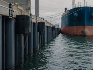
Place the fender so its center aligns with the vessel’s point of first contact. For quay-side installations, the fender should sit at mid-tide waterline height. For ship-to-ship transfer operations, position fenders along the parallel body of the larger vessel.
When using multiple fenders, space them evenly across the berthing face. A common guideline is to use one fender per 30–50 meters of vessel length, with a minimum of two fenders per berth.

Step 3: Inflate to Working Pressure
Follow this procedure:
- Remove the inflation rod from the fender toolbox and connect it to the valve
- Use a wrench to remove the valve core
- Connect the air source (compressor or manual pump) via a quick connector
- Inflate slowly to the rated working pressure — either 50 kPa (0.05 MPa) or 80 kPa (0.08 MPa) per ISO 17357-1:2014
- Close the valve, verify pressure with a calibrated gauge
- Reinstall the valve core and check for leaks
Important: Inflate slowly and monitor pressure continuously. Over-inflation increases reaction force and risks damaging the fender or the vessel hull. Under-inflation reduces energy absorption, causing the fender to “bottom out” on impact.
Common Mistakes to Avoid
Even experienced operators make these errors. Each one reduces fender performance or causes premature failure:
- Incorrect inflation pressure. Temperature changes affect internal pressure. A fender inflated to 50 kPa at 15°C may reach 58–60 kPa at 35°C. Check pressure before each berthing operation and adjust seasonally.
- Poor fender positioning. If the vessel contacts the fender off-center or at the fender’s end cap, the energy is not absorbed evenly. This can cause localized damage to both the fender and the hull.
- Ignoring chain/net condition on CTN fenders. A damaged tire net or corroded chain can separate from the fender body during berthing. Inspect the net and all shackle connections before deployment.
- Dragging fenders across rough surfaces. Moving inflated fenders across concrete quays or rocky ground causes abrasion damage to the outer rubber. Always lift fenders using proper rigging — never drag them.
- Storing inflated fenders in direct sunlight. UV radiation degrades rubber over time. Deflate fenders for long-term storage and keep them in a shaded, dry area. Apply talcum powder to prevent surface adhesion.

Routine Maintenance Schedule
Regular maintenance extends fender life and ensures reliable protection. Follow this schedule:
| Check | Frequency | What to Look For |
|---|---|---|
| Air pressure | Before each use | Pressure within ±5 kPa of rated value |
| Surface condition | Monthly | Cracks, cuts, deep abrasion, bulges |
| Valve and fittings | Monthly | Leaks, corrosion, damaged threads |
| Chain/tire net (CTN type) | Quarterly | Corrosion, broken links, loose shackles |
| Wire rope slings (Sling type) | Quarterly | Broken wires, corrosion, deformation |
| Full pressure test | Annually | Inflate to 1.25× working pressure, hold 30 minutes, check for leaks |
Henger After-Sales Support: All Henger pneumatic fenders ship with a maintenance toolbox including an inflation rod, valve cores, pressure gauge, and a repair kit. Our technical team provides free maintenance guidance throughout the product lifecycle.
Conclusion
Proper use of pneumatic fenders comes down to three fundamentals: correct sizing, correct installation, and consistent maintenance. Get the size right using berthing energy calculations. Install with the appropriate securing method and verify inflation pressure before every operation. Maintain on schedule to catch problems early.
At Henger Shipping Supplies, we support customers from initial fender selection through installation guidance and long-term maintenance. Whether you need standard pneumatic fenders, foam filled fenders, or marine airbags, our engineering team is ready to help you find the optimal solution.
Frequently Asked Questions
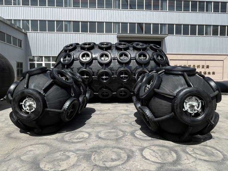
CTN (Chain-Tire Net) fenders have a protective outer net of used tires connected by chains. They are designed for permanent installations and high-traffic ports where the fender is exposed to repeated impacts and abrasion. Sling-type fenders are lighter, easier to reposition, and better suited for temporary berthing, STS transfers, and locations where fenders need to be moved frequently.
These are the two standard internal pressure grades defined by ISO 17357-1:2014. At the same physical size, an 80 kPa fender absorbs more energy and produces higher reaction force than a 50 kPa fender. The 50 kPa grade is suitable for most general cargo and tanker berths. The 80 kPa grade is used when higher energy absorption is needed in a compact fender size.
Typical service life is 8–12 years with proper maintenance. Factors that shorten lifespan include excessive UV exposure, chemical contact, over-inflation, and impacts beyond the rated energy capacity. Henger fenders are manufactured with UV-resistant rubber compounds and multi-layer synthetic cord reinforcement to maximize durability.
Yes, but pressure adjustments are necessary. Internal air pressure increases in hot weather and decreases in cold weather. Check and adjust pressure whenever ambient temperature changes by more than 15°C from the inflation baseline. Henger fenders are rated for continuous operation from -25°C to +60°C.
If a fender shows a slow leak, mark its position and monitor the pressure drop rate. A minor leak (less than 5 kPa per hour) may allow the fender to complete the current berthing operation. For rapid pressure loss, replace the fender immediately with a standby unit. After the operation, inspect the valve, fittings, and rubber surface to identify the leak source. Small punctures can often be repaired on-site. For major damage, consult the manufacturer.